Introduction
This post outlines the advantages of integrating a type 3 wind farm into an electricity grid alongside solar sources. The argument is usually made to have the strengths of wind energy compensate the weaknesses of solar energy. Bear in mind that the 3 components typically discussed under the term “integration costs” of wind and solar energy are grid costs, balancing costs and the cost effects on conventional power
Characteristics of a Type 3 WTG
Figure 1 below shows the general components of a Type 3 Wind Turbine Generator (WTG).
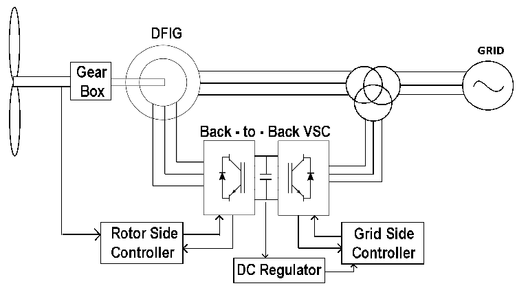
Source: https://www.researchgate.net/figure/Schematic-Doubly-Fed-Machine-based-Type-3-Wind-Turbine-System_fig1_282818786
Type 3 WTG is variable speed with partial power electronics in the form of a back-to-back converter. It operates between the cut-in, rated and cut-out wind speeds. This converter is usually only rated at 30-40% of the generator and employs sinusoidal or space vector PWM.. Type 3 WTGs can vary reactive power at a given active power and terminal voltage, thereby enabling voltage control. It is commonly known as the Doubly Fed Induction Generator (DFIG) or Doubly Fed Asynchronous Generator (DFAG) that employs variable frequency AC excitation to rotor circuit. As such, the generator’s magnetizing current can either be provided by the grid or the voltage source converter.
The DFIG has the following advantages [7]:
- Higher efficiencies
- Decoupled control and real and reactive power
- Reduced noise compared to other types WTG
- Reduce mechanical stresses thereby reducing maintenance costs
- Does not require reactive compensation devices
- Better performance during voltage dip, transient time and other disturbances compared to other variable speed generators [10]
The DFIG has the following disadvantages:
- The direct connection of the stator to the grid leaves the machine more vulnerable to system disturbances. Requires an over-current ‘crowbar’ to protect itself
The DFIG is quite popular, currently having a large world market share approximately above 70% [10]. Their power ranges are typically between 1.5 – 6 MW. These WTGs are conceptualized as variable speed “synchronous generators” with bus-fed excitation. The voltage source regulator is current regulated, able to adjust rotor’s currents’ magnitude and phase instantaneously. They are modelled as a voltage source behind subtransient reactance. Electrical components contain: machine-side converter and controller, grid-side converter and controllers, DC-link system including chopper, low pass filter
[amazon_auto_links id=”2211″]Striking a Balance
Achieving high levels of solar and wind integration will require coordinated planning of generation and transmission development. Strategic, economic curtailments of solar and wind energy can enhance system flexibility as these curtailments occur in all high RE scenarios [3]. Solar and wind cannot be switched on based on demand and are often built far away from high demand areas. The PV system yield depends, in addition to the site conditions, on the sun’s angle on the surface, installed capacity, technology and occurring losses whereas the yield of onshore wind power plants basically depends on the hub height, rotor diameter, capacity, wind speed, losses and availability of the plant. The differences between these 2 sources of energy can complement each other in a local electricity grid. Wind farms possess higher capacity factors than solar farms as shown in Table 1 obtained from a study performed in the Philippines. This is due to the effects of cloud cover and the diurnal nature of solar energy.

WTGs play a crucial role to RE grid integration since most grid codes require reactive power capability at the point of interconnect over a specified power factor range. Type 3 WTGs typically have a reactive power capability from pf 0.95 lagging (capacitive) to 0.90 leading (inductive) at the terminals of the machines. The Grid Side Converter is a bidirectional rectifier bridge, responsible for maintaining the DC bus voltage within limits by transferring the power from the rotor, which is stored in the DC-link capacitor, to the grid [7]. It also exchanges reactive power with the grid by either absorbing reactive power from the grid or exporting reactive power to the grid as per the set value.
Frequency Regulation
The increased penetration of RE sources brings a new set of challenges and can be argued to have a negative effect on traditional grids. On such challenge is frequency control. Frequency variations in power systems can lead to a severe decrease in power quality resulting in equipment damage and safety concerns. Consider the equation below.
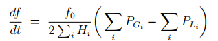
Where:
f0 – nominal frequency (Hz)
Hi- total system inertia (MVAs)
PGi- generated power (MVA)
PLi- consumed power (MVA)
The equation above shows that a low inertia system will experience larger frequency deviations during disturbances thereby making frequency control increasingly difficult with increasing inverters penetration. Traditional generators possess high inertia that inherently handles frequency regulation well. The inertia contribution from wind turbines can aid frequency regulation. If a solar farm is expected to perform frequency/voltage regulation, a storage system along with suitable control strategies must be implemented.
Fault Behaviour
Short-circuit analysis is important to protect coordination as well as assess fault-current withstand requirements [1]. Industry’s short-circuit analysis practices and tools are based on synchronous generators. Consequently, current connection impact assessments rules were built on years of rotating machines experience and often misrepresent inverter based sources [6].
In the case of a solar farm, PWM inverters can quickly cease delivering power to the grid by stopping gating the power devices [6]. When dealing with short circuits, the two decision-making mechanisms for disconnection are under-voltage and over-current measurements. Inverter based solar farms can increase the fault current level of distribution substation or primary networks beyond the permissible short-circuit capacity of substation/feeder equipment [6].
Figure 2 shows the short circuit current behaviour of a Type 3 WTG.
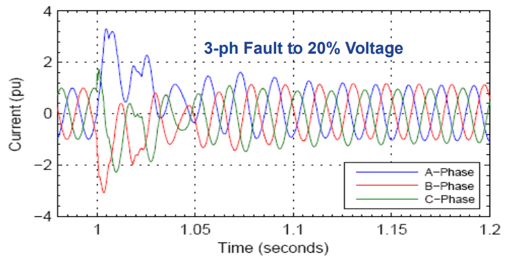
Table Comparison
| Pros for Wind | Cons against Wind |
| During abnormal conditions, can increase or decrease shaft speed/kinetic energy to satisfy system needs | Wind farms require significantly higher land use. (See table 1). Study in philippines used 135 W/m^2 for solar and 3W/m^2 for wind |
| Rapid response – short time delays compared to directly connected magnetic machines, with winding time constants | A study in germany predicts a technology learning rate of 15% for solar and 3% for onshore wind |
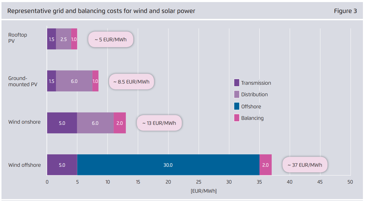
| Turbine can be used for frequency response, solar would require a battery system to provide this. | Grid and balancing costs are higher for wind than solar integrations as observed from a study in germany [5] |
| Wind integrations possess much high capacity factors than solar farms (See table 2) | In countries with high amounts of air conditioning, there is usually a strong correlation of solar irradiation and electricity demand |
| During a fault, the machine stator currents would be limited between 1.1 to 2.5 pu of the machine rated current | WTGs usually possess have high maintenance cost from manufacturers |
| Theoretically infinite duration low-voltage ride-through capability | Energy output from solar installations is easier to predict than wind due to less variables in calculation |
| Able to perform droop control | WTGs usually have a lower warranty of 5-10 years compared to solar installation at 10-25 years |
| Significant localized growth in PV can raise concerns such as voltage violations and reverse power flow in LV distribution systems | WTGs produces high amounts of noise as opposed to the silent operation of solar farms |
| Solar farm output being diurnal puts a strain on forecasting system inertia needs | Wind farms can be seen for miles and is controversial amongst residents in the area as opposed to solar farms which is less disruptive |
| Solar farm provides no inertia to system thereby increasing the rate of change of frequency in fault scenarios | Type 3 WTG is quite difficult to model even though modelling of synchronous generators is mature |
| Solar energy storage is expensive if voltage and frequency regulation is needed | |
| Converter for DFIG is significantly cheaper as it is rated to 30-40% of generator | |
| Lower rated converter also translates to lower power losses thereby improving system efficiency | |
| Less harmonics injected into grid since output is a clean AC waveform. Solar farm inverters will produce harmonics that are a factor of the switching frequency |
Supplementary Material
References
[1] – http://www.ieee.ca/epec11/admin/S03.pdf[2] – http://home.eng.iastate.edu/~jdm/wesep594/Full-converter%20WTG%20Technology.pdf
[3] – https://www.nrel.gov/docs/fy18osti/68594.pdf
[4]- https://www.sciencedirect.com/science/article/pii/S1876610216316617
[5] – https://pdfs.semanticscholar.org/cc01/0230fcdc5fc371e031c3ab8ef1d90ddd25a1.pdf
[6] – https://ieeexplore.ieee.org/stamp/stamp.jsp?tp=&arnumber=6009218
[7] – https://www.nrel.gov/docs/fy12osti/52780.pdf
[8] – https://ieeexplore.ieee.org/document/8521003
[9] – https://www.hindawi.com/journals/je/2017/2918281/
[10] – https://pdfs.semanticscholar.org/7a03/ea4a170ac381168cd7b4ffab7ddd9abcc8c4.pdf